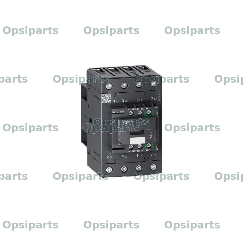
Repräsentatives Komponentenbild, kein Foto dieser exakten Marke oder Teilenummer. Spezifikation bestätigen; das gelieferte Teil kann anders aussehen.
LC1DT80ABBE — Contactor
SchützTeilenummer: LC1DT80ABBE
LC1DT80ABBE — Contactor — Schneider Electric reference LC1DT80ABBE. Request a quotation including shipping to your destination. Send equipment details and certificate requirements so we can confirm the exact specification, fitment, availability and warranty terms before ordering.
Sie suchen Schneider Electric LC1DT80ABBE? Diese Katalogreferenz ist als „Schütz“ eingeordnet. Senden Sie die Teilenummer und Ihre Gerätedaten, damit wir Spezifikation und Verfügbarkeit prüfen und ein Angebot inklusive Versand erstellen können.
Verfügbarkeit auf Anfrage
Technische Daten
| Hersteller | Schneider Electric |
|---|---|
| Teilenummer | LC1DT80ABBE |
| Kategorie | Elektrotechnik & Steuerungen |
| Range | TeSys TeSys Deca |
| Range of Product | TeSys Deca |
| Product or Component Type | Contactor |
| Poles description | 4P |
| [Ue] rated operational voltage | Power circuit <= 690 V AC 25...400 Hz |
| [Ie] rated operational current | 80 A (at <140 °F (60 °C)) at <= 440 V AC-1 for power circuit |
| [Uc] control circuit voltage | 24 V DC |
| [Ith] conventional free air thermal current | 80 A (at 140 °F (60 °C)) for power circuit 10 A (at 140 °F (60 °C)) for signalling circuit |
| Irms rated making capacity | 1000 A at 440 V for power circuit conforming to IEC 60947 140 A AC for signalling circuit conforming to IEC 60947-5-1 250 A DC for signalling circuit conforming to IEC 60947-5-1 |
| Rated breaking capacity | 1000 A at 440 V for power circuit conforming to IEC 60947 |
| [Icw] rated short-time withstand current | 110 A 104 °F (40 °C) - 10 min for power circuit 260 A 104 °F (40 °C) - 1 min for power circuit 520 A 104 °F (40 °C) - 10 s for power circuit 900 A 104 °F (40 °C) - 1 s for power circuit 100 A - 1 s for signalling circuit 120 A - 500 ms for signalling circuit 140 A - 100 ms for signalling circuit |
| Associated fuse rating | 125 A gG at <= 690 V coordination type 1 for power circuit 125 A gG at <= 690 V coordination type 2 for power circuit 10 A gG for signalling circuit conforming to IEC 60947-5-1 |
| Average impedance | 1.6 mOhm - Ith 80 A 50 Hz for power circuit |
| Power dissipation per pole | 10.2 W AC-1 |
| [Ui] rated insulation voltage | Power circuit 690 V IEC 60947-4-1 Signalling circuit 690 V IEC 60947-1 |
| Overvoltage category | III |
| [Uimp] rated impulse withstand voltage | 6 kV IEC 60947 |
| Control circuit voltage limits | <= 0.1 Uc (-40…158 °F (-40…70 °C)):drop-out DC 0.8...1.2 Uc (-40…140 °F (-40…60 °C)):operational DC 1...1.2 Uc (140…158 °F (60…70 °C)):operational DC |
| Inrush power in W | 11 W 68 °F (20 °C)) |
| Hold-in power consumption in W | 0.5 W 68 °F (20 °C) |
| Operating time | 55...65 ms closing 20...80 ms opening |
| Maximum operating rate | 3600 cyc/h at 60 °C |
| Connections - terminals | Control circuit: screw clamp terminals 1 0.002…0.006 in² (1…4 mm²) - cable stiffness: flexible without cable end Control circuit: screw clamp terminals 2 0.002…0.006 in² (1…4 mm²) - cable stiffness: flexible without cable end Control circuit: screw clamp terminals 1 0.002…0.006 in² (1…4 mm²) - cable stiffness: flexible with cable end Control circuit: screw clamp terminals 2 0.002…0.004 in² (1…2.5 mm²) - cable stiffness: flexible with cable end Control circuit: screw clamp terminals 1 0.002…0.006 in² (1…4 mm²) - cable stiffness: solid Control circuit: screw clamp terminals 2 0.002…0.006 in² (1…4 mm²) - cable stiffness: solid Power circuit: EverLink BTR screw connectors 1 0.002…0.05 in² (1…35 |
| Tightening torque | Control circuit 15.05 lbf.in (1.7 N.m) screw clamp terminals flat Ø 6 mm Control circuit 15.05 lbf.in (1.7 N.m) screw clamp terminals Philips No 2 Power circuit 70.8 lbf.in (8 N.m) EverLink BTR screw connectors 0.04…0.05 in² (25…35 mm²) hexagonal 0.2 in (4 mm) Power circuit 44.3 lbf.in (5 N.m) EverLink BTR screw connectors 0.002…0.04 in² (1…25 mm²) hexagonal 0.2 in (4 mm) Power circuit 44.3 lbf.in (5 N.m) pozidriv No 2 Control circuit 15.05 lbf.in (1.7 N.m) pozidriv No 2 |
| Auxiliary contacts type | Mechanically linked 1 NO + 1 NC IEC 60947-5-1 Mirror contact 1 NC IEC 60947-4-1 |
| Signalling circuit frequency | 25...400 Hz |
| Minimum switching voltage | 17 V for signalling circuit |
| Minimum switching current | 5 mA for signalling circuit |
| Published component type | Contactor |
| Reference status | Published part reference; specification and fitment require confirmation |
| Availability | On request |
Katalogangaben können fehlerhaft oder veraltet sein. Vollständige Spezifikationen und geprüfte Angaben erhalten Sie auf Anfrage. Bitte bestätigen Sie vor der Bestellung die Teilenummer und die Eignung für Ihre Maschine mit uns.
Fragen zum Produkt
Für dieses Teil liegen noch keine Rechercheergebnisse auf Deutsch vor. Unser Team hilft Ihnen gerne weiter.
Angebot für dieses Teil erhalten