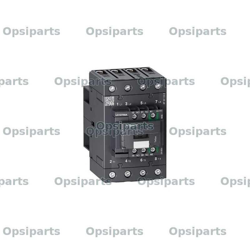
Poglądowe zdjęcie typu części, nie fotografia tej dokładnej marki ani numeru katalogowego. Potwierdź parametry; dostarczona część może wyglądać inaczej.
LC1DT60ABBE — Contactor
stycznikNumer części: LC1DT60ABBE
LC1DT60ABBE — Contactor — Schneider Electric reference LC1DT60ABBE. Request a quotation including shipping to your destination. Send equipment details and certificate requirements so we can confirm the exact specification, fitment, availability and warranty terms before ordering.
Szukasz części Schneider Electric LC1DT60ABBE? Ta pozycja katalogowa jest sklasyfikowana jako „stycznik”. Prześlij numer części i dane maszyny, abyśmy mogli sprawdzić parametry i dostępność oraz przygotować ofertę z dostawą w cenie.
Dostępność na zapytanie
Specyfikacja techniczna
| Producent | Schneider Electric |
|---|---|
| Numer części | LC1DT60ABBE |
| Kategoria | Elektryka i sterowanie |
| Range | TeSys TeSys Deca |
| Range of Product | TeSys Deca |
| Product or Component Type | Contactor |
| Poles description | 4P |
| [Ue] rated operational voltage | Power circuit <= 690 V AC 25...400 Hz |
| [Ie] rated operational current | 60 A (at <140 °F (60 °C)) at <= 440 V AC-1 for power circuit |
| [Uc] control circuit voltage | 24 V DC |
| [Ith] conventional free air thermal current | 60 A (at 140 °F (60 °C)) for power circuit 10 A (at 140 °F (60 °C)) for signalling circuit |
| Irms rated making capacity | 800 A at 440 V for power circuit conforming to IEC 60947 140 A AC for signalling circuit conforming to IEC 60947-5-1 250 A DC for signalling circuit conforming to IEC 60947-5-1 |
| Rated breaking capacity | 800 A at 440 V for power circuit conforming to IEC 60947 |
| [Icw] rated short-time withstand current | 72 A 104 °F (40 °C) - 10 min for power circuit 165 A 104 °F (40 °C) - 1 min for power circuit 320 A 104 °F (40 °C) - 10 s for power circuit 720 A 104 °F (40 °C) - 1 s for power circuit 100 A - 1 s for signalling circuit 120 A - 500 ms for signalling circuit 140 A - 100 ms for signalling circuit |
| Associated fuse rating | 80 A gG at <= 690 V coordination type 1 for power circuit 80 A gG at <= 690 V coordination type 2 for power circuit 10 A gG for signalling circuit conforming to IEC 60947-5-1 |
| Average impedance | 1.6 mOhm - Ith 60 A 50 Hz for power circuit |
| Power dissipation per pole | 5.8 W AC-1 |
| [Ui] rated insulation voltage | Power circuit 690 V IEC 60947-4-1 Signalling circuit 690 V IEC 60947-1 |
| Overvoltage category | III |
| [Uimp] rated impulse withstand voltage | 6 kV IEC 60947 |
| Control circuit voltage limits | <= 0.1 Uc (-40…158 °F (-40…70 °C)):drop-out DC 0.8...1.2 Uc (-40…140 °F (-40…60 °C)):operational DC 1...1.2 Uc (140…158 °F (60…70 °C)):operational DC |
| Inrush power in W | 11 W 68 °F (20 °C)) |
| Hold-in power consumption in W | 0.5 W 68 °F (20 °C) |
| Operating time | 55...65 ms closing 20...80 ms opening |
| Maximum operating rate | 3600 cyc/h at 60 °C |
| Connections - terminals | Control circuit: screw clamp terminals 1 0.002…0.006 in² (1…4 mm²) - cable stiffness: flexible without cable end Control circuit: screw clamp terminals 2 0.002…0.006 in² (1…4 mm²) - cable stiffness: flexible without cable end Control circuit: screw clamp terminals 1 0.002…0.006 in² (1…4 mm²) - cable stiffness: flexible with cable end Control circuit: screw clamp terminals 2 0.002…0.004 in² (1…2.5 mm²) - cable stiffness: flexible with cable end Control circuit: screw clamp terminals 1 0.002…0.006 in² (1…4 mm²) - cable stiffness: solid Control circuit: screw clamp terminals 2 0.002…0.006 in² (1…4 mm²) - cable stiffness: solid Power circuit: EverLink BTR screw connectors 1 0.002…0.05 in² (1…35 |
| Tightening torque | Control circuit 15.05 lbf.in (1.7 N.m) screw clamp terminals flat Ø 6 mm Control circuit 15.05 lbf.in (1.7 N.m) screw clamp terminals Philips No 2 Power circuit 70.8 lbf.in (8 N.m) EverLink BTR screw connectors 0.04…0.05 in² (25…35 mm²) hexagonal 0.2 in (4 mm) Power circuit 44.3 lbf.in (5 N.m) EverLink BTR screw connectors 0.002…0.04 in² (1…25 mm²) hexagonal 0.2 in (4 mm) Power circuit 44.3 lbf.in (5 N.m) pozidriv No 2 Control circuit 15.05 lbf.in (1.7 N.m) pozidriv No 2 |
| Auxiliary contacts type | Mechanically linked 1 NO + 1 NC IEC 60947-5-1 Mirror contact 1 NC IEC 60947-4-1 |
| Signalling circuit frequency | 25...400 Hz |
| Minimum switching voltage | 17 V for signalling circuit |
| Minimum switching current | 5 mA for signalling circuit |
| Published component type | Contactor |
| Reference status | Published part reference; specification and fitment require confirmation |
| Availability | On request |
Informacje katalogowe mogą zawierać błędy lub być nieaktualne. Pełne specyfikacje i zweryfikowane dane są dostępne na życzenie. Przed zamówieniem potwierdź z nami numer części i jej dopasowanie do maszyny.
Pytania o produkt
Wyniki badań dotyczących tej części nie są jeszcze dostępne po polsku. Skontaktuj się z naszym zespołem.
Uzyskaj wycenę tej części